Inline Monitoring
A thermal camera that understands what it sees, a digital twin that knows what should happen next, and a controller that acts on the difference. This is how OTOM brings AFP from monitored to self-correcting.
Thank you for reading this post, don't forget to subscribe!A thermal camera alone shows the surface, not the bond line, and only after the fact. A simulation alone predicts but cannot see what is really happening. OTOM joins the two: real-time thermal image processing feeds a physics-based digital twin, and a model-based controller turns the gap between measurement and prediction into the next laser setting.
The loop: see, understand, decide, act
Live camera streams or recordings are read frame by frame and corrected for emissivity and reflected temperature.
Feature tracking keeps the probes on the moving nip point, and line profiles reveal gradients across the tape.
The model predicts the coming temperature and the controller chooses the laser power that holds the target.
Set-points go to the machine over TwinCAT ADS, and process values come back for the next cycle.
Real-time thermal camera image processing
The IR Cam module in AFP Web reads thermal-camera data as the camera’s own software does, including Optris recordings that match PIX Connect. Then it does what a camera viewer cannot:
- Radiometric correction: whole-image or per-probe emissivity and reflected temperature, applied through Planck’s law.
- Adaptive nip-point tracking: feature tracking and learning frames move the probes with the nip point, so they do not drift onto the tape or the substrate.
- Simulation overlay: the simulated nip point and temperature field are laid over the IR image for direct comparison.
- Probes, multiple line profiles and reports: temperature against time and along lines, exported frame by frame.
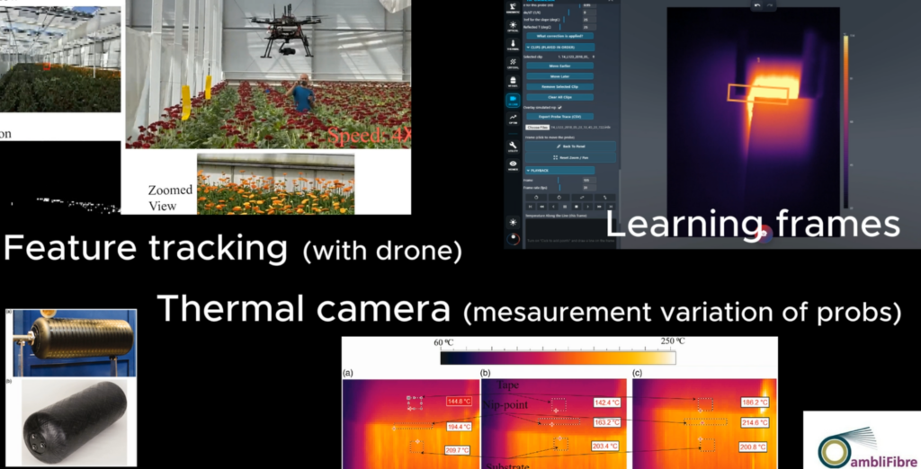
AI-enhanced thermal-camera feature tracking for AFP.
The model controller of the AFP digital twin
The digital twin knows the geometry ahead of the head: where curvature changes, where the laser will be shadowed, where earlier plies have left heat behind. The controller uses that foresight instead of reacting after the temperature has already drifted.
Predictive power schedules
Sensitivity, Quick and Instant methods plan laser power over the coming steps to minimise temperature bumps or hold a target, within a maximum power change per step and a bonding floor.
Target holding
Each station is solved against the lay-up as the head finds it, including heat accumulated from earlier courses.
Model predictive control
The OTOM engine predicts future process outputs and finds the control action that drives them to the reference, for consistent quality from part to part.
Proven on the machine: OTOM and TwinCAT
The link to the shop floor goes back to OTOM V.1.08, tested at the OTOM Composite centre. Data passes between OTOM and Beckhoff TwinCAT XAE over ADS, a secure and fast channel, so a monitoring cycle fits in a fraction of a millisecond. The engine runs in two forms: GUI mode for engineers, and Batch mode, which a third-party application or data-mining algorithm can drive through files or direct access to the model data. In the demonstration, velocity and laser power inputs from TwinCAT are processed live and the calculated tape and substrate temperatures are returned to the PLC.
Where we are heading
Our goal is AFP that corrects itself: every course monitored, understood and adjusted while it is being laid, with a digital record of how each part was made.
Bring your thermal recordings
Send us a recording from your machine, and we will show you the tracked nip point next to its digital twin.